

Bernard H. Geyer
August 11, 2004
Office of Air research Automatic Computer (OARAC)
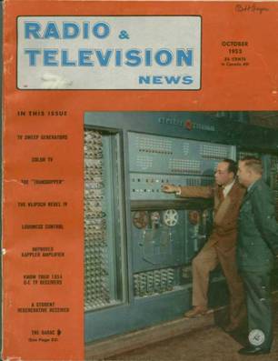
October, 1953
Reproduced from “Radio & Television News”
October 1953
Charles R Wayne and AF General Leighton I. Davis
with OARAC in background
Office of Air research Automatic Computer (OARAC)
October, 1953
by Bernard H. Geyer
Electronics Laboratory, General Electric Co,. Syracuse, NY
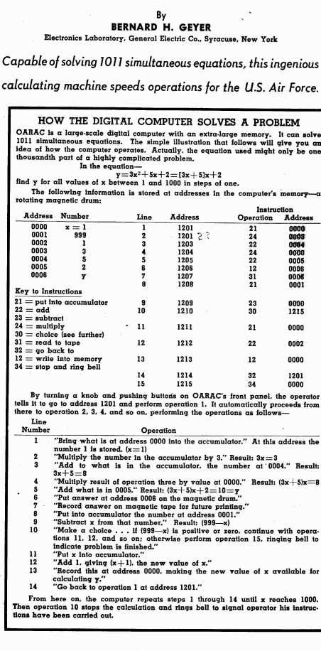
THE OARAC (Office of Air Research Automatic Calculator) is an electronic calculating machine (illustrated on this month’s cover) designed and built for the U.S. Air Force by the General Electric Company. It is capable of solving the most complex mathematical problems at speeds which seem fantastic to those not acquainted with the principles of electronics. It may be said that OARAC has a 10,000 word memory with an average access time of 9 milliseconds, that it I. can multiply two ten-digit numbers in - approximately 8 milliseconds, that it can add two such numbers in less than 100 microseconds, and that it can perform as many as 100 arithmetic operations per second. It might, however, be more informative to look into this 1400 tube electronic giant with the eyes of a layman who has never heard of a 10,000 word memory or a 9 millisecond access time. One of the first things to come to the attention of our hypothetical lay- man would be the OARAC memory
.
OARAC’S Memory
This part of the computer (some call it the “brain” or “heart” of the machine though that is hardly justified) centers around an aluminum cylinder 22” in diameter and 30” long. This cylinder rotates at a speed of 3350 rpm and is coated with a magnetic oxide similar to that found on the tapes used in magnetic tape recorders. Approximately 200 magnetic record-playback heads are spaced along the axis of the cylinder approximately 0.002” from its surface. When a positive or negative electrical pulse is applied to one of these heads the magnetic surface of the cylinder immediately adjacent to the head is magnetized to form a positive or negative magnetic spot. Each of the 200 heads can write 2600 such spots around the circumference of the cylinder That is a total of 200 x 2600 520,000 I The same head reads back a positive or negative electrical signal whenever one of the magnetic spots passes beneath it. Thus it may be seen that once a spot has been recorded on the cylinder it is available to be read back once each drum revolution there- after. In the language of electronic computers, each of these 520,000 magnetic spots represents one “bit” (binary digit) of information. In the OARAC a group of 52 bits is called a word space, hence it may be seen that the OARAC memory contains 10,000 word spaces. Thus we say that OARAC has a 10,000 word memory. Since each spot on the memory cylinder passes under a magnetic head only once for each revolution of the cylinder, it is not possible to read any arbitrary spot at any arbitrary time. It may be necessary to wait up to a full revolution before the desired spot passes beneath a magnetic head. Since the cylinder rotates at 3350 rpm or approximately 56 revolutions per second, one revolution takes 1/56 second or approximately 18/1000 second which is 18 milliseconds. This is the maximum access time for the memory. The waiting time for the desired spot (or more properly “word” since a full word is always read at one time) to be read may vary from zero up to the maximum access time of 18 milliseconds, hence it is useful to speak of the average waiting time. This is just 1/2 the maximum access time, thus we say that the average access time is 9 milliseconds.
The Mainframe - Arithmetic
Turning away from the OARAC memory our layman encounters a large cabinet filled with vacuum tubes, germanium diodes, and associated electronic components not to mention an almost undecipherable maze of wires. The contents of this cabinet are primarily the arithmetic and control circuits of the computer. In spite of their electronic complexity, the basic functions of these circuits are quite simple. Let’s consider the arithmetic unit first. The arithmetic unit is that part of the computer which does the arithmetic calculation. It may be com- pared to a very high-speed desk calculator which is capable of adding two ten-decimal-digit numbers in about 90/1,000,000 of a second, or in computer language, 90 microseconds. The multiplication of two such numbers takes approximately 8/1000 second or 8 milliseconds. The main components of the arithmetic unit are three storage registers, an adder, and a counter. The storage registers are electronic circuits (each contains 44 tubes plus 352 germanium diodes and associated components) each of which is capable of storing one ten-decimal-digit number, or word as it is sometimes called. These registers are used to store numbers temporarily while the arithmetic operations are being carried out. The adder may be compared to an electronic addition table. When electrical signals representing two numbers are fed to its input an output signal representing the sum of the two numbers appears at its output terminals. When the adder is properly connected to two of the three storage registers, the numbers stored in the registers are added and the sum is stored in one of the registers. Subtraction is accomplished by first making one of the numbers negative and then adding them. Multiplication is accomplished by means of repeated additions. For example, 7 x 3 = 21 may be written 7 + 7 + 7 = 21. Using this method, multiplication makes use of the adder and the counter is used to keep track of the number of additions that are made. This is a somewhat simplified version of how the computer actually multiplies, but it serves to illustrate the basic principle involved.
The Mainframe – Control & Sequencing
The control circuits of OARAC may be divided into two parts—the arithmetic controls and the sequencing circuits. The arithmetic control circuits send the necessary signals to the arithmetic unit to cause it to add, subtract, divide, etc. as required. The sequencing circuits are the real heart of the computer. It is this part of the machine which governs the automatic operation and so to speak “bosses” the rest of the computer. Before a problem is turned over to OARAC for solution, a mathematician must break it down into a series of simple steps such as additions, multiplications, etc., which the computer can execute. The computer is told to carry out each of these steps (and a typical problem might have several thousand steps many of which the computer repeats hundreds or even thousands of times) by means of an instruction for each step. An instruction is essentially a code number which tells the computer what to do. For example, 220005 is an instruction telling the computer to add (code 22) the number stored in the memory at word space 0005 to the number al- ready in the arithmetic unit. When the problem is put on the computer, the list of instructions together with the necessary numbers is stored in the memory. Each instruction or number is stored at a specified address in the memory. (The word spaces in the memory are all numbered and these numbers are called addresses.) After the problem is stored in the memory the computer is placed in operation from the control panel by specifying the address of the first instruction to be executed. The sequencing circuits send out the necessary signals to cause the first instruction to be read from the memory. When it has been read back from the memory, the sequencing circuits interpret it and send out the necessary signals to the arithmetic control circuits to cause them to execute the instruction. After the instruction has been carried out, the arithmetic control circuits send a signal back to the sequencing circuits. When the sequencing circuits receive this signal they automatically cause the next instruction to be read back from the memory, interpret it, and signal the proper section of the arithmetic control to carry it out. This cycle continues at a rate up to 100 instructions per second until an instruction to stop is reached, or until an error occurs which causes the computer to stop. The computer is so built that it automatically detects most of the errors which it occasionally makes and automatically corrects many of them. If the computer cannot correct its error by repeating the computation it stops and signals the operator by means of an alarm bell. The operator then corrects the trouble and restarts the computer.
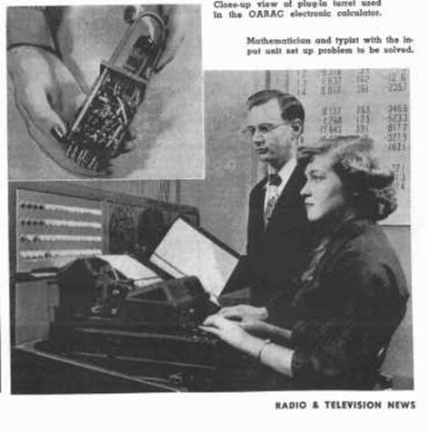
.Secretary at the input typewriter with one of the Air Force programmers,
Carl Fluke, observing her work
Extracted From
Ballistic Research Laboratories
“A Third Survey of Domestic Electronic Digital Computing Systems”
March, 1961
http://ed-thelen.org/comp-hist/BRL61.html#TOC
OARAC
Office of Air Research Automatic Computer
MANUFACTURER
General Electric Company
APPLICATIONS
Scientific computation and analysis.
PROGRAMMING AND NUMERICAL SYSTEM
Internal number system Binary coded decimal
Decimal digits/word 10 + sign
Decimal digits/instruction 7
Instructions/word 1
Instructions decoded 21
Instructions used 21
Arithmetic system Variable fixed decimal point loca-
tion, can be set to any of 11 dig-
it positions initially. It must
remain at this location during any
given sequence of operations, in
order to obtain consistent results.
Instruction type Two address (The machine originally
was a one address machine). The
modification to a two address ma-
chine facilitated access to stor-
age and permitted execution of
special instructions with signifi-
cant savings in time.
Number range Variable + (1010 - 1)
Number system used is the 2*-4-2-1 system.
ARITHMETIC UNIT
Incl Stor Access Exclud Stor Access
Microsec Microsec
Add 400-17,000 91
Mult 10,000-26,000 800
Div 10,000-26,000 1,200
Construction
Vacuum tubes 400
Diodes 2,500
Basic pulse repetition rate 150 Kc/sec
Arithmetic mode Serial by character
Parallel by bits
Timing Synchronous
Operation Sequential
STORAGE
No. of No. of Access
Media Words Digits Microsec
Magnetic Drum 10,000 110,000 1,000-17,000
Magnetic Tape 7,200 per 1,200 ft.tape
INPUT
Media Speed
Magnetic Tape 1,000 words/min
Keyboard Manual
Keyboard is located on main control panel.
OUTPUT
Medium Speed
Magnetic Tape 1,000 words/min
Contents of tape translated by an off-line code
transcriber and typewriter.
CIRCUIT ELEMENTS OF ENTIRE SYSTEM
Tubes 1,200
Tube types 12
Crystal diodes 7,000
Separate cabinets 2
Computer is housed in one cabinet and the magnetic drum is
housed in another cabinet.
CHECKING FEATURES
Exceed capacity
Unprogrammed stop
Wrong combination
Synchronized tape
Divide by zero
Product exceed capacity
Tape runout, power and cooling failure fault checks.
POWER, SPACE, WEIGHT, AND SITE. PREPARATION
Power, computer 23 KVA
Volume, computer 600 cu ft
Area, computer 80 sq ft
Weight, computer 6,000 lbs
Capacity, air conditioner 10 Tons
The two cabinets measure 15 by 2.5 by 7 ft. and 4 by 5 by
6 ft.
PRODUCTION RECORD
Number produced 1
This system was developed on a research and development
contract for the Air Force.
COST, PRICE AND RENTAL RATES
Approximate cost of basic system $185,000.
RELIABILITY, OPERATING EXPERIENCE,
AND TIME AVAILABILITY
Average error-free running period 15 Hours
Good time 13,686 Hours
Attempted to run time 16,733 Hours
Operating ratio (Good/Attempted to run time) 0.82
Above figures based on period from Apr 53 to Apr 56
Passed Customer Acceptance Test Apr 53
ADDITIONAL FEATURES AND REMARKS
The OARAC has been improved. The improved version
reportedly uses the same codes and commands as OARAC in
order that problems may be run without difficulty.
The problem exists with most computer installations that a
considerable amount of machine time is required for checking out
problems and it is planned to compensate for this by using the new
machine, which is faster than the old OARAC, for running checked-
out problems only.
The new machine is supposed to have a 10,000 word core
memory, and is supposed to be able to perform additions in 65
microseconds, excluding access time or in 130 microseconds,
including access time and playback of the next instruction,
multiply in 2.6 milliseconds and divide on an average of 6
milliseconds. This is supposed to result in an operating time
savings of approximately 25 to 1 for most programs.
INSTALLATIONS
Aeronautical Research Laboratory
Wright Air Development Center
Wright-Patterson Air Force Base, Ohio